Account
BEAM
Northavon Business Center, Dean Road, Yate, Bristol, BS37 5NH
Tel: (01454) 324512 Fax: (01454) 313172 Email: beam@beam.demon.co.uk
Specification for Bristol University
Radio Astronomy FFT Processor
AstroFFT
Ref: spec7
Date: 10/8/01
Introduction
This is a specification for the Bristol University Radio Astronomy FFT processing system (AstroFFT). The purpose of the system is to enable researchers to survey the Galactic plane looking for H20 Masers at 22 GHz using a Radio Telescope situated at Bristol University. Signals received from the Radio Telescope need to be processed in order to pick out the signature spectrum from the large level of noise. This requires processing large amounts of data at a fast real-time rate, integrating the results over a long period and storing the results in data files that can be further processed by researchers.
Processing System Specification
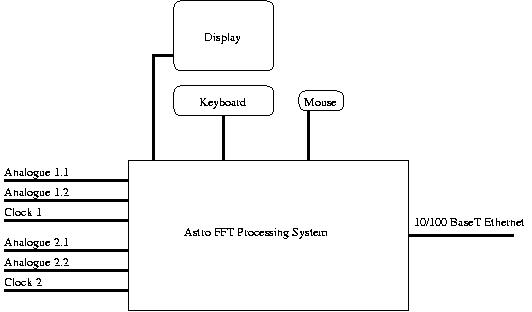
The system will consist of a 4u high 19inch rack-mount processing unit with external monitor, keyboard and mouse.

The processing system will consist of a dual Pentium III host computer system with two FPGA based FFT processing engines mounted in a 19inch rack case. Each FPGA processing engine will have two analogue and one digital clock input. The system will be linked to other systems by means of a 10 BaseT / 100 BaseT Ethernet network interface. The host system will have a display, keyboard and mouse for local operation and maintenance. It will be possible to operate the unit locally or remotely via the network interface.
Most of the high speed processing will be performed by the FPGA computer engines. The host system will be responsible for overall system control, low speed data post processing and data storage and transfer.
The host system will run the Linux operating system and provide the full features of this system including the ability for users to develop applications to control the system and/or process the data. However, the system will also be able to be used as a stand-alone black box system controlled from another computer through the network interface.
Processing Engine Specification
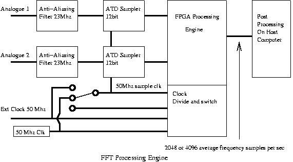
The system will consist of two separate FFT processing engines implemented on two separate FPGA based hardware boards. Each processing engine will have two Analogue to Digital samplers, feeding into a large FPGA and will be connected to the PCI bus of the host computer.
In order to achieve the high number of frequency sample outputs required an analogue quadrature mixer may need to be employed, prior to the FPGA processing engine, to convert the telescopes 25Mhz bandwidth signal into two signals in quadrature. This will probably need to be the case if 4096 frequency samples are required at the output unless a real mode FFT algorithm can be fitted onto the FPGA. The quadrature mixer may not be required when 2048 frequency samples are required if the chosen bit resolution of 4096 point FFT will fit into the FPGA. The two quadrature signals will be fed to the two analogue to digital samplers.
Each processing engine will have the following features:

· Two Analogue Inputs through SMB connectors. Each input will take accept a 1v p-p signal over a bandwidth of 1 KHz to 25 MHz -1dB and have a 50 ohm input impedance. Each input will have a separate analogue ground fed into differential inputs.
· Each analogue input will have an anti-aliasing filter with a cutoff frequency of 23Mhz (-0.5db) and at least -20db at 25 MHz with a maximum of +- 0.5db ripple within the pass band. It may be possible to make this programable by component selection to a degree.
· Each analogue input will have a single order high pass filter with a cut off frequency of 500 Hz (-3db).
· Each analogue input stage will have the same physical geometry in order to minimise any phase or other differences between the two analogue input stages.
· Each processing engine will have an external digital clock input through a SMB connector. This will be fed to a differential input buffer and will accept a digital clock of 0-5V and will have an input impedance of 100 ohm. The frequency of this clock will be 50MHz but can be reduced to 1.5625 MHz which will lower the sample rate and FFT result frequency spacing accordingly.
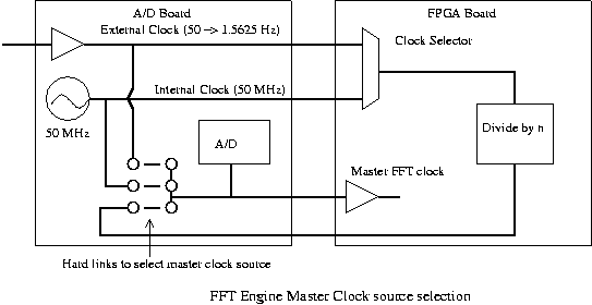
· The processing engines master sample clock can be derived from one of three sources by means of a jumper on the A/D board. In one setting the user input clock will be directly used, in another setting the on-board 50 MHz clock will be directly used, in the final setting a clock produced by the FPGA will be used. The FPGA generated clock will be derived from either the external or on-board 50 MHz clock source, the choise of which will be software selectable. The FPGA generated clock will be able to be divided down to provide the following output frequencies: 50MHz, 25MHz, 12.5MHz, 6.25MHz, 3.125MHz and 1.5625MHz, this will be software selectable. It is expected to use the internal clock source fed through the FPGA divider, but if there are problems with jitter then the direct external clock can be used. It is important for the A/D process that the sample clock has low jitter, so the external clock, on-board clock and divider should be chosen to reflect this. A diagram of the master clock system is shown below.

· Each filtered analogue input will be sampled at the sample clock frequency by a 12 bit analogue to digital convertor. The full 12 bits will be passed to the FPGA. The FPGA will use the top N bits of the input. The actual number, N, of bits used will equal or be less than the internal data resolution of the FFT process.
· The FPGA will accept the two 12bit sampled channels and the master sample clock and perform the FFT calculation and integration of the magnitude of the resulting frequency components.
· The FFT engine will perform a continuous complex 4096 point FFT on the sampled analogue inputs.
FFT Algorithm
The FFT engine's internal data resolution will be a minimum of 13 bits for each of the real and imaginary components. Adaptive scaling will be used in the FPGA to improve the bit resolution of the overall FFT process. It is expected to use a radix-4 algorithm.
The algorithm will use two's complement fixed point arithmetic, values will thus be in the range +-0.9999. In all cases where bits of data are discarded (fixed point multiplications and scaling of the data) the value of the data will be rounded to the nearest value. The radix-4 butterfly operations will yield higher resolution (number of bits) results. These results will be either scaled down (bits shifted down) or the upper bits will be ignored depending on the adaptive scaling's prediction.
The actual adaptive scaling system has yet to be decided, but a possible system is as follows: On the first FFT pass the radix-4 butterfly results will be divided by 8. Each butterfly result, real and imaginary after scaling, will be tested to see if its magnitude is greater than or equal to 0.125. If any result is greater than or equal to this then the butterfly results of the next pass will be divided by 8. If no result is greater than or equal to 0.125 then the butterfly results of the next pass will not be scaled, instead the top 3 bits will be discarded. On each divide by 8 scaling an overall FFT scaling flag will be incremented to indicate the scaling of the resultant data.
FFT Basic Mode Functionality
The FPGA processing engine will be able to be set into one of a number of modes as listed below. It is expected the system will support the QFFT, FFT and Analogue modes. The FFT mode is considered a fallback mode in case there are problems with the analogue quadrature mixer. If further research into the RFFT mode makes it practiable to fit the necessary post processing into the FPGA, then the modes available will be the RFFT and Analogue modes.
FFT Mode: In this mode a single ATD convertor will sample a single analogue data stream at 50Mhz. The ATD samples will be fed into the real inputs of a 4096 point FFT using fixed point math. This will generate 4096 complex frequency samples. A following integrator will take first 2048 of these samples. The magnitude of each complex frequency sample, formed by squareing the real and imaginary parts separately and then adding them, is added to an intergrating buffer. After a given number of FFT runs have been processed and added to the integrator the integrated results are passed to the host. If a radix-4 algorithm is used a single butterfly would need to perform 6 passes and run at 75 MHz.
QFFT Mode: In this mode a twin ATD convertors will sample the two analogue data streams at 25Mhz. The ATD samples will be fed into the real and imaginary inputs of a 4096 point FFT using fixed point math. This will generate 4096 complex frequency samples. A following integrator will take all of the 4096 samples. The magnitude of each complex frequency sample, formed by squareing the real and imaginary parts separately and then adding them, is added to an intergrating buffer. After a given number of FFT runs have been processed and added to the integrator the integrated results are passed to the host. If a radix-4 algorithm is used a single butterfly would need to perform 6 passes and run at 37.5 MHz.
RFFT Mode: In this mode a single ATD convertor will sample the single analogue data stream at 50Mhz. Alternate ATD samples will be fed into the real and imaginary inputs of a 4096 point FFT using fixed point math. This will generate 4096 mixed complex frequency samples. A following post processing filter will take these samples and produce 4096 frequency samples. A following integrator will take all of the 4096 samples. The magnitude of each complex frequency sample, formed by squareing the real and imaginary parts separately and then adding them, is added to an intergrating buffer. After a given number of FFT runs have been processed and added to the integrator the integrated results are passed to the host. If a radix-4 algorithm is used a single butterfly would need to run at 37.5 MHz.
Analogue Mode: In this mode both ATD convertors will sample at 50Mhz. The 12 bit samples will be bit extended with 0's at the lower end to form 16 bit values. The two 16 bit values will be combined into a 32 bit value and fed to the host. The FPGA will also calculate the RMS power and the number of ATD peak values of each data stream and pass this to the host with each set of samples.
Processing engine configuration parameters
| Parameter | Setting | Description |
| Clock | 0 or 1 | Internal clock or external clock |
| Sample frequency | 0 through 5 | 50Mhz -> 1.5625 MHz |
| Mode | 0,1, 2, 3, 4 | FFT, QFFT, CFFT, RFFT, Analogue Mode |
| Number of Cycles | <number> | This programs how many FFT's will be averaged within the FPGA before a data set is sent to the host. |
| Run | 0 or 1 | Start running |
| Clock | 0 or 1 | Internal clock or external clock |
System Software
The FFT system software will consist of a main control process and three command interface processes. The main control process will be responsible for managing the FPGA processing engines and data storage. The command interface processes will enable users or other computer software to control the main control process. The processes will perform the following work:
1. The main control process. This will startup when the system is booted and will run continually while the system is in operation. It is responsible for booting and controlling the FPGA processing engines and performing data post processing.
2. Network socket interface. This will enable remote computers to send commands to the FFT system. ASCII text based commands will be supported that could be sent via a Telnet session or a computer program on the remote computer.
3. Command line interface. This will enable a user or local program to send commands to the FFT system.
4. Graphical User Interface. This X-Windows based application will allow users to control the FFT system and view interim results.
The main control parameters will be as follows:
| Parameter | Setting | Description |
| Clock | 0 or 1 | Internal clock or external clock |
| Sample Frequency | 0 through 5 | 50Mhz -> 1.5625 MHz |
| Mode | 0,1, 2, 3, 4 | FFT, QFFT, CFFT, RFFT, Analogue Mode |
| Number of Cycles | <number> | This programs how many FFT's will be averaged within the FPGA before a data set is sent to the host. |
| Title | String | Title for next run |
| File Name | String | File name for next run |
| File Format | Binary or ASCII | The File format. Either 32bit binary values or ASCII values |
| Average Number | 1 -> n | Sets the number of FPGA averaged results that are further averaged in the software processing. |
| Number of samples | 1 -> 8.64 million | Total number of averaged FFT samples collected in the run. Time from 1s to 10 days. |
| Run | 0 or 1 | Start or stop the run |
| Pause | 0 or 1 | Pause the storage of data in the file. Saves a time mark describing the paused period. |
The system will perform a complete run based on the parameters setup. Information on the run and the raw sample data will be stored into two files on the systems disk drive. The information file will contain information on the parameters used and the run start and stop times. The data file will contain the data in binary or ASCII formats. The ASCII format will consist of lines each storing a complete FFT average output with comma separated sample values.
The data files will be stored in a directory which can be mounted from a remote system using either NFS or Microsoft Windows SMB protocols. This will allow remote systems to access the data from the processing runs.
Time Control
The system will have a local time clock which can be synchronised to a remote time server on the local area network using the network time protocol NTP. It would also be possible to upgrade with a GPS time reference board if required.
System Security
Normal high levels of system security will be provided by the Linux operating system. Remote access will be password protected.
