Account
| |  Astronomical FFT processing systemSystem Hardware installation |
Introduction
This document describes how to install the Astro FFT system hardware.The Astro FFT system comprises a single 19" rack mountable dual Pentium III PC running the linux operating system. Installed within the unit are the two PCI, FPGA based data aquisition and processing cards. The aquisition cards are in fact three seperate cards - An ADC-PMC-64 PMC-PCI carrier board connected into a one of the PC PCI slots. This carrier card has an PMC format A/D (Analogue to Digital) convertor and ADM-XRC FPGA reconfigurable computer cards loaded.


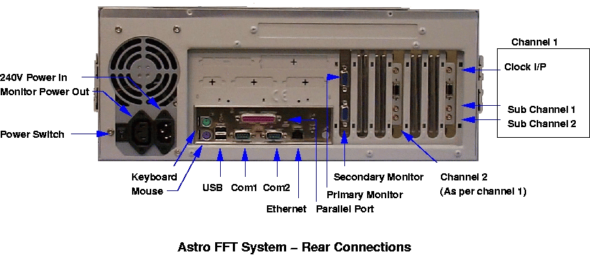
The unit has the following external connections :-
| Function | Connector Type | Comment |
|---|---|---|
| Keyboard | PS/2 | Standard PC Keyboard |
| Mouse | PS/2 | 3 Button PS/2 data format |
| Com1 | D-Type 9 way | Serial port com1 |
| Com2 | D-Type 9 way | Serial port com2 |
| Parallel port | D-Type 25 Way | |
| USB | USB | Universal serial bus |
| Ethernet | RJ45 | 10/100Mb/sec Ethernet Connect to switch |
| Monitor1 | D-Type 15 way | Primary display |
| Monitor2 | D-Type 15 way | Secondary display |
CHANNEL1
| SMB | Aquisition external sample clock 0-5V 1.56 - 50MHz |
| SMB | Aquisition data channel 1 50 Ohms differential,1V Pk-Pk BW 1KHz -25MHz -1db |
| SMB | Aquisition data channel 2 50 Ohms differential,1V Pk-Pk BW 1KHz -25MHz -1db |
| Direct access to A/D FPGA Module | |
CHANNEL2
| SMB | Aquisition external sample clock 0-5V 1.56 - 50MHz |
| SMB | Aquisition data channel 1 50 Ohms differential,1V Pk-Pk BW 1KHz -25MHz -1db |
| SMB | Aquisition data channel 2 50 Ohms differential,1V Pk-Pk BW 1KHz -25MHz -1db |
| Direct access to A/D FPGA Module |
Ethernet Switch
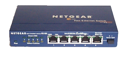
When the unit has processed data, this data is made available via a network to additional computers. Since potentially a large volume of data can be transmitted a wire speed 5 port ethernet switch is provided. Into this switch should be connected the AstroFFT unit, the remote control/data collation PC, and the local network. Using this scheme ethernet traffic between the AstroFFT and the control PC does not appear on and hence does not load the local network. Connection to the swtich are made via the front panel. Ports 1 to 4 are interchangeable as is port 5 provided the ulink button is set to the NORMAL position. Power to the switch is made using the DC adapter supplied. Netware installation guide.

