
Account
Blacknest BDS Data Overview
| Date | 2008-03-06 |
| Version | 0.7 |
Note that this is a "work in progress" document and is being continually updated.
Introduction
This document provides an overview of the seismic data and meta data that the BDS system needs to process.Terminology
Quite a lot of terminology is used seismic instrumentation. Some of this is conflicting. For the BDS system we will use the following terminology:| Term | Description |
|---|---|
| Array | Name of an array of Stations having seismometers and other sensors. This has a location. A single name is given for both Arrays and Stations. |
| Station | A single measuring site that can have a number of instruments. This has a location which is time dependent. It is also sometimes referred to as a Site. |
| Instrument | A single measuring instrument that can have a number of channels. |
| Channel | A single measuring channel that will return a single set of data. It has an associated Instrument, Digitiser and Sensor. Each channel has a calibration value. |
| Digitiser | A digitiser that digitises the analogue signals from a Sensor. A digitiser can support multiple sensors and also have multiple output channels at differing sample rates. It has an associated set of filter frequency responses for the Anti-aliasing and other processing functions. |
| Sensor | A per channel, seismometer, hydrophone or other sensor measuring time-dependent data, e.g. temperature, wind speed. It has a frequency response and other associated parameters such as installation angles. |
| Network | This defines an organisation that is responsible for a number of seismic Arrays/Stations or provides data for a number of Arrays. Each Network organistaion may have its own database with different settings for various parameters such as CalibrationFactor. |
| PAZ | Poles and Zeros table for frequency response |
| FAP | Frequency Amplitude Phase table for frequency response |
| FIR | Finite Impulse Response coefficient table for frequency response |
| CalibrationFactor | A measured or set value that defines the gain of a channel from physical Earth movement to numeric value at a particular frequency. |
| Event | A seismic disturbance, e.g. and earthquake or explosion. |
| Arrival | An "arrival" is a signal from an earthquake or explosion recorded at a station. |
- Arrays and Stations are normally sinominous with each other. A single name is used to define them. The location of an array is the centre of the effective beam.
Instrument Response MetaData
An Array consists of a number of seismic measuring Stations. Each seismic measuring Station has a location and a number of channels of data provided by a number of Instruments. Each Instrument can measure data on a number of Channels.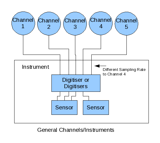
Each digitiser will have an initial and final SampleFrequency and an associated set of filters with appropriate frequency responses on a per channel basis. The main filter of interest is normally the final anti-aliasing filer used prior to final time domain decimation.
Each Sensor has a set of parameters including the frequency response.
The Sensors frequency response is the overriding one, The Digitisers response is fairly "flat" over the region of interest compared to the seismometers frequency response and are thus the Digitisers responses are not normally taken into account.
A calibration value, CalibrationFactor, is entered into the system on a per channel basis. This value is defined for a particular CalibrationFrequency and defines the scaling over the entire channel from seismometer movement to digitised value in file. This factor allows the seismic movement values to be expressed in nanometers. The value is sometimes measured or sometimes the manufactures scaling values for the Digitiser and Sensor are used.
If a user wants basic seismic data they simply multiply each samples value by the CalibrationFactor value.
If a user wants more detail they can get the frequency response of the seismometer and perhaps the other filters, normalize these at the CalibrationFrequency and apply the inverse transformation to the data set as well as multiply by the CalibrationFactor value.
The following tables provide a possible, high level, ordered list of the information available. It's order is based on the overall structure of the system. It is a high level list and does not provide detailed information.
Network
This defines an organisation that is responsible for a number of seismic Arrays or provides data for a number of Arrays. Each Network organistaion may have its own database with different settings for various parameters such as CalibrationScale.
| Item | Description |
|---|---|
| Id | Unique integer ID |
| Name | The Network name. |
| Arrays[] | The list of Arrays/Stations used by this Organisation. |
Array
A seismic measuring array that consists of a number of Stations.
| Item | Description |
|---|---|
| Id | Unique integer ID |
| Name | The Arrays unique name. (YKA etc) |
| Location | Location: latitude and longitude in degrees using the WGS84 datum, the ground level elevation in meters from the WGS84 ellipsoid (Sea level). |
| Stations[] | The list of stations within this array |
Station
A location where a set of instruments is located.
| Item | Description |
|---|---|
| Id | Unique integer ID |
| Name | The Stations name. (A Pit name) |
| Locations[] | Location: latitude and longitude in degrees using the WGS84 datum, the ground level elevation in meters from the WGS84 ellipsoid (Sea level). (IDC standard is a little vague on this - we will have to check, and might need information to denote the standard(s) used. The geographical information about a site is usually quite static.) This is a list of locations with a TimePeriod for each location as Stations can be moved. |
| TimePeriods[] | A list of time periods the Station was operation. |
| Channels[] | A list of all of the data channels available at this site. |
Channel
An individual data channel.
| Item | Description |
|---|---|
| Id | Unique integer ID |
| Name | The channel name. (Such as SHZ, BHZ) |
| Calibration[] | Calibration measurements. A list of calibration measurements by date |
| Instruments[] | The set of Instruments used by date |
Instrument
A measuring instrument that can have a number of channels. An instrument may be a physical device or it could be fictitious if seperate digitisers and sensors are used.
| Item | Description |
|---|---|
| Id | Unique integer ID |
| Name | The instruments name. |
| Model | The instruments model name. The Vendor make/type of instrument. Only used when there is a unique instrument model |
| SerialNumber | The instrument's serial number. |
| LocationId | An ID for the location of the instrument. (Such as "00" for the borehole and "10" for the position on "Pier 1" in the vault at Wolverton) (This might be Name and therefore could be removed). |
| Digitisers[] | The Digitisers used. A list of Digitisers by date. (An instrument may have an integrated digitiser which does not change) |
| Sensors[] | The Sensors used. A list of sensors by date. (An instrument may have an integrated sensor which does not change) |
Digitiser
The digitiser used. In reality the sensor/digitiser could be a single unit. Digitisers can support multiple channels.| Item | Description |
|---|---|
| Id | Unique integer ID |
| TimePeriod | The time period the digitiser was in use |
| Name | The digitiser name. (This may not be needed) |
| Model | The digitiser model name. The Vendor make/type of instrument |
| SerialNumber | The digitiser's serial number |
| SamplingFrequencys[] | The frequency of sampling in HZ per channel |
| InitialSamplingFrequencies[] | The initial frequency of sampling in HZ per channel |
| Responses[] | Array of responses for each channel. (Anti-aliasing filter, Digitiser, post filter etc) |
| Gain | The gain setting. For information only. Set to 0 if unknown. (One per channel ??) |
Sensor
A measurement sensor. This would be a seismometer or could be another unit such as a Hydrophone. A Sensor could have multiple channels.
| Item | Description |
|---|---|
| Id | Unique integer ID |
| TimePeriod | The time period the sensor was in use |
| Name | The sensor name. (This may not be needed) |
| Type | The sensors type. (Seismometer, Hydrophone etc) |
| Model | The sensors model name. The Vendor make/type of sensor |
| SerialNumber | The sensors serial number |
| Responses[] | Frequency response of sensor as an array of pole zero values or as an amplitude/phase table for each channel. |
| PlacementAngle | The Seismometer placement horizontal angle in degrees clockwise from north and vertical angle in degrees with zero = vertically up |
| Depth | The depth of the unit below ground level |
| Gain | The gain setting. For information only. Set to 0 if unknown. |
Calibration
A calibration measurement.
| Item | Description |
|---|---|
| Id | Unique integer ID |
| TimePeriod | The time period the factor was in use |
| CalibrationFrequency | The frequency that the CalibrationScale value is valid for |
| CalibrationFactor | The scaling value to apply to the data to normalise to Nanometers. This is a measured value at the calibration frequency and is in Nanometers/Count. |
Response
A frequency response. This can store the response as a pole/zero table, an amplitude/phase table or a set of FIR coefficients.
| Item | Description |
|---|---|
| Id | Unique integer ID |
| Name | The response name. (Sensor, AntiAlias, Digitiser) |
| PoleZeros | Frequency response defined by an array of pole zero values in radians per second. |
| AmplitudePhaseTable | Frequency response defined by an array of amplitude/phase values with respect to frequency. |
| FirCoefficients | Frequency response defined by an array of coefficients. |
| Gain | The overall gain of the filter (At what frequency ???) |
| Decimation | The amount of decimation applied ?? |
| GroupCorrectionApplied | The group delay correction applied in seconds ?? |
| Symmetry | Symmetry for FIR coefficients (A = asymmetric, B = symmetric[odd], C = symmetric[even]) ?? |
- This is a high level overview based on the physical structure of the measuement system.
- No information has been included as to the Network (Organisation). This would allow the choice of different sets of parameters dependent on the Organisation's own settings.
- It may be worth pre-calculating the sensors pole/zero normalisation scale value (CalibrationFactor) and storing this in a cache for performance reasons.
Data Storage Meta Data
There needs to be information on the available data sets stored in the archive. The following this the important information that is required:| Item | Description |
|---|---|
| Id | Unique integer ID |
| Network | The Network organisation the original data is from |
| Array/Station | The Array/Station the data is from. |
| TimePeriod | The time period of the data |
| Source | Some information on the source of this data. This would allow multiple sources of data from the same Array and Period. It could also support processed data. the source of this data. This would allow multiple sources of data from the same Array and Period. It could also support processed data. (DIRECT, TAPE, PROCESSED ...) |
| Location | The location of the data. This could be a local archive or even a remote archive |
| Type | The type of the data, basically the data format. |
| URL | File location. This can embody a protocol, host, path and filename. |
| Comment | A general comment string |
- For any given Array/Station and Period there can be multiple sets of data. This can come from different Network sources and also could include pre-processed data.
- The Array/Station and Period information would be used to lookup the Channel and Instrument information from the Instrument Response Meta Data.
- We may need to add information here on the channels contained in the dataset. This could include channel swaps etc.
Event Meta Data
There is a fair amount of information to be stored for seismic Event handling. The main information, as from the IDC data base, has the following database tables:| Arrival | General information on an Arrival from an event. |
| Stassoc | Summary information on groups of Arrivals. |
| Origin | Information on the derived origin of events. |
| Expio | Information on explosions |
The event information system will need some looking at, however its information can be separated from the main BDS data. The only link between the two data sets will probably be the time period of the event.
- It may be useful to store processed data sets in the main BDS system linked to particular events.
Other Meta Data
There is a number of other items of Meta Data to be stored. The main sets of these include:| System Outages | Information on known system outages |
| User Information | User ID and other login and security information |
| Data Request Queuing | Data request queuing and bandwidth management |
| Logs/Statistics | Logs and statistics of use |
| Notes | This could be a list of notes on the Meta Data that can be added for information |
Most of these items content is dependent of the operation of the BDS itself. They are not crucial to the Seismic data itself.
Seismic Raw Data
The seismic data consists of a number of channels of sampled seismic amplitude values from an Array's Stations. The seismic data is stored in files in various formats. It is proposed that the BDS should initially be able to handle the following formats:External Data Formats
| BKNAS 1.0/2.0 | The Blacknest standard data format 1.0 and 2.0 |
| IMS 2.0 | The IDC IMS data format |
Data Storage Formats
| BDRS | BDRS data files are comprised of 4012 byte blocks, each containing a 6 byte header, 4000 data bytes, containing 100 data points from each of 20 channels in two byte blocks, plus 6 footer bytes. |
| WRA | WRA40, WRA64 and WRA-AGSO. |
| GCF | Guralp compressed format. File and streaming format. |
| CD-1.1 | IDC Streaming data format |
| SEED | Standard for the Exchange of Earthquake Data format. |
| TapeDigitiser | The Blacknest TapeDigitser file format for Digitised Analogue Tapes. |
The following provides the core features of these formats.
TapeDigitiser
| Overview | Developed for the TapeDigitiser project to store information from sampled old analogue tapes. Contains a lot of Meta Information about the quality of tape and digitisation process. |
| Structure | ASCII header. Normally 24 Channels, blocked in variable length blocks of about 12.5 seconds of data per block. |
| Raw data format | 32bit floating point multiplexed data |
| Sampling Rate | 100Hz, but can vary due to tape speed fluctuations (~0.1%) |
| Meta Data | Meta data on Array and Tape name, time, and details of the Tape Digitisation process. |
| Misc | Two channels are error channels, one channel is a VELA time-code channel. |
| Amount |
BKNAS
| Overview | Blacknest AutoDRM data format. Available in Version 1.0 and 2.0. No compression. |
| Structure | Up to 35 Channels of continuous data. Multiplexed ASCII data. One set of channel samples per line. |
| Raw data format | ASCII Integer |
| Sampling Rate | 20Hz normally |
| Meta Data | Array/Station, Channels, Original Data Type, MasterTapeNumber, TapeFileNumber, Location (no depth), Event information, Geographic region number and name, DigitisingOffset?, |
| Misc | Cannot provide all of the information that will be available. |
| Amount |
- BKNAS1 imposes some limits on the number of channels. Subroutine "afdtr.f" which reads in BKNAS 1 and 2 data for "Apple" (which is our only program that seriously uses BKNAS-format data) has array size 35 for the arrays containing the channel information. Also the digital samples are read in with format statement "40I6", which both imposes a limit of 40 channels and restricts the dynamic range to 9x10^5 digital counts.
IMS 2.0
| Overview | IDC AutoDRM data format. Available in Version 1.0 and 2.0. Compressed or un-compressed. |
| Structure | Up to 35 Channels of continuous data. Separate sets of data per channel. |
| Raw data format | This can be in: INT(ASCII Integers), CM6(compressed integers described in 6bit ASCII), CM8(compressed integers described in 8bit ASCII), CSF(a sub-format for authenticated data) |
| Sampling Rate | Any |
| Meta Data | Network, Station, Channels StationCode, FDSN ChannelCode, AuxCode, InstrumentType, CalibrationScale, CalibrationFrequency, SampleRate, Start/Stop times, PAZ/FAP/FIR Tables, Event information |
| Misc | Maximum 100MByte message size, can have multiple messages using a REF_ID field. Maximum line length 1,024 characters. |
| Amount |
BDRS
| Overview | Very old and basic data storage format. No compression. |
| Structure | 4010 byte Block based, with simple header (Part of array name + Date/Time only). 20 Channels of data. |
| Raw data format | 16bit Integer in little-endian binary format. |
| Sampling Rate | Normally 20Hz |
| Meta Data | None other than Part of an array name and Date/Time (Just last digit of year) |
| Misc | The directory path and file name is used to define the Array, the Year and Day. |
| Amount |
WRA 40 and 64
| Overview | Old basic data storage format. No compression. |
| Structure | WRA40: 32768 Byte blocks with a 256Byte header. 40 Channels of data. WRA64: 53248 Byte blocks with a 256Byte header. 64 Channels of data. |
| Raw data format | Binary 16bit signed values in little-endian format. |
| Sampling Rate | 20Hz ? |
| Meta Data | None other than Date/Time |
| Misc | The directory path and file name is used to define the Array, the Year and Day. |
| Amount |
WRA-AGSO
| Overview | Old basic data storage format, but with compression. |
| Structure | ASCII file header followed by 256 Byte binary data blocks or 256 Byte ASCII blocks. |
| Raw data format | 16bit signed integers in double-difference compressed format identical to that used in GSE2.1 CM8 (Same as IMS CM8?). Non-multiplexed data (one channel at a time). |
| Sampling Rate | 20Hz |
| Meta Data | StationCode, SamplingRate, ChannelName, CalibrationFactor |
| Misc | The directory path and file name is used to define the Array, the Year and Day. |
| Amount |
GCF
| Overview | Guralp compressed format. Designed for streaming data as well as storage. A low level compressed format with little MetaData. |
| Structure | A file or stream format. Consists of a sequence of variable length blocks, which can be up to 1024 bytes long. Blocks define data for an individual channel. |
| Raw data format | Compressed Binary either: 32-bit differences, 16-bit differences or 8-bit differences |
| Sampling Rate | Defined in block headers |
| Meta Data | SystemId, StreamId, Date/Time, SamplingRate, |
| Misc | The block duration is always a whole number of seconds, and always starts on a whole second boundary. |
| Amount | Being fed by Satellite |
CD-1.1
| Overview | IDC Streaming data protocol. A low level compressed format with little MetaData. |
| Structure | A stream format. Consists of a sequence of variable length frames. Frames broken info individual segments which contain data for each channel. |
| Raw data format | Compressed or Un-Compressed Binary either: 32-bit differences, 16-bit differences or 8-bit differences. Separate channels multiplexed in individual frames. |
| Sampling Rate | No defined |
| Meta Data | Date/Time, Station, Channel |
| Misc | |
| Amount | May be fed by Satellite in the future |
SEED
| Overview | This is an extensive well thought out format. It provides full data and meta-data capability. It is quite complex and big. It is a bit old fashioned in places and looks like it would be awkward to use. |
| Structure | Blockette based. This is a variable length lump of information with an integer type field. The file consists of a sequence of headers andvariable numbers of Blockette's. Blockette's describe data, and meta information. |
| Raw data format | Various ASCII and binary, compressed and non-compressed formats are provided. There may be issues with multiplexed channel data. The SEED manual states that is is not desirable to usemultiplexed channel data in SEED files although it is possible. |
| Sampling Rate | Any |
| Meta Data | Full meta-data available and can be extended (with some difficulty). |
| Misc | May not support streaming that well. Would be difficult to add additional meta-Data although it can be done. |
| Amount |
Some notes on these data formats:
The BDRS, WRA-40, WRA-64 and TapeDigitiser are uncompressed formats. If there is a large amount of these they should be stored in a compressed format.
- Only the SEED and TapeDigitiser formats have any appreciable ability to store Meta Information.
- The BDRS, WRA-40, WRA-64, WRA-AGSO, GCF and TapeDigitiser formats can easily be stored in another format without any loss of information. Due to the extensive abilities of the SEED format, some loss of information could be incurred when storing in another format unless that format has the same abilities.
Compression
- Have a look at the IMS CM6 compression system.
- Some good descriptions of some methods in the SEED manual:
CODES 10 - 29 FDSN Networks
10 STEIM (1) Compression
11 STEIM (2) Compression
12 GEOSCOPE Multiplexed Format 24 bit integer
13 GEOSCOPE Multiplexed Format 16 bit gain ranged, 3 bit exponent
14 GEOSCOPE Multiplexed Format 16 bit gain ranged, 4 bit exponent
15 US National Network compression
16 CDSN 16 bit gain ranged
17 Graefenberg 16 bit gain ranged
18 IPG - Strasbourg 16 bit gain ranged
19 STEIM (3) Compression
- What levels of compression are possible, we need to store a set of example data in the different formats ?
Notes
- All Station Codes in the world should be unique and registered with the ISC in the United Kingdom/the National Earthquake Information Center (NEIC) in the United States ? Answer: This is not always the case but they are unique per Network. (Should be to USG85 ?)
- Channel code standards are defined in the IMS "Formats and Protocols for Messages" document. Also in the SEED manual. Are all codes to these rules ? Answer: Yes, we will use these codes. There may be some two letter codes such as BZ or SZ, or in lower case, bz, sz, which will be converted. (Should be to IRI93 ?)
- There are some Instrument type codes defined in the SEED manual (Appendix A). Are all codes to these rules ?
- The IMS format has information on Elevation and Depth. Why are the two given ? Answer: The "depth" value tells the seismologist that an instrument is in a borehole. This is useful information. The elevation is required for e.g. synthetic seismogram calculation. So both values are required.
- I note that the SEED format has the possibility of flagging that a Leap Second occurred during a block of data. Do we need to handle Leap Seconds ? Answer: Handling Leap Seconds would be good. GPS time does not include Leap Seconds, although a regularly broadcast message notes how far GPST and UTC are apart.
- What date time accuracy should we use: Seconds, Milli-Seconds ? Answer: Milli-Seconds.